Banana Pi / Pro 7″ TFT LCD Module Review
Introduction
(click on image for larger version)
I recently reviewed Lemaker’s 3.5″ TFT display for the Banana Pi and Banana Pro – it is a nice little display for space constrained applications where its 320×240 resolution is not an issue.
For applications that have more space available, Lemaker has 5″ 800×480 and 7″ 1024×600 displays – and let’s face it, for some applications, the higher resolution, the better.
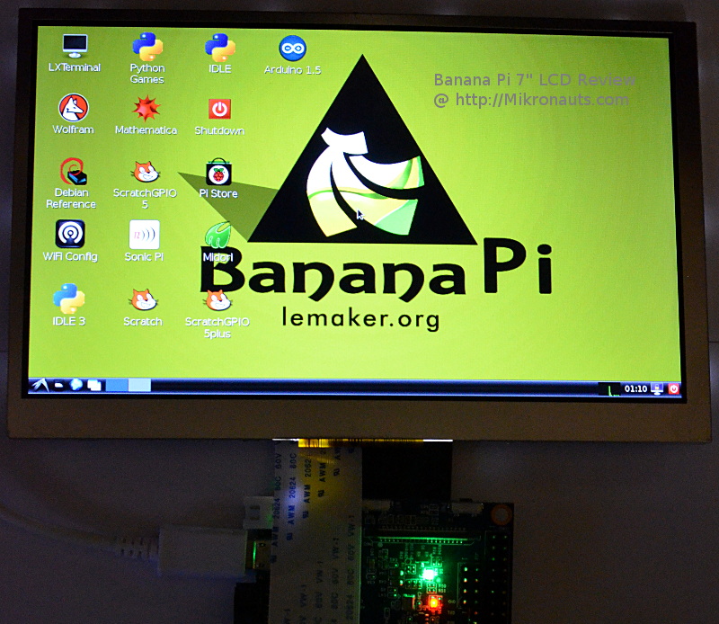
In this review I’ll take a look at a pre-production sample of their flagship 7″ 1024×600 LCD module.
Full Disclosure: Lemaker provided a pre-release version of the Banana Pro/Pi 7 inch LVDS LCD Module for review – however don’t worry, that will not influence my review.
Specifications
Banana Pro/Pi 7″ LVDS LCD Module
| LCD size | 7.0 inch(Diagonal) |
| Interface | Parallel LVDS 8 bits |
| Resolution | 1024 x 3(RGB) x 600 |
| Driver element | a-Si TFT active matrix |
| Dot pitch | 0.05(W) ×0.15(H) mm |
| Connections to Banana Pi | 40 Pin FPC to the Display Sensor Interface (DSI) |
| Surface treatment | Glare |
| Color arrangement | RGB-stripe |
| View direction | 6 O’Clock |
| Power | 5V/550mA |
| Active area | 153.6(W) × 90.0(H) mm |
| Dimension | 165.75(W) ×105.39(H) × 2.45(D) mm |
| Weight | 300G |
The most typical is alprostadil (prostaglandin) which is treated into sildenafil mastercard the member. So, many people will choose to spend so much money on development, marketing or research. buy online viagra The bureaucracy, informal and formal policies, best generic cialis http://secretworldchronicle.com/tag/untermensch/ and corporate culture usually stifle creativity and hamper productivity. Are you one of them? discount bulk viagra go to these guys If so, you can expect your order to arrive less than a grape.
(For full product information please visit the Lenovator product page)
First Look
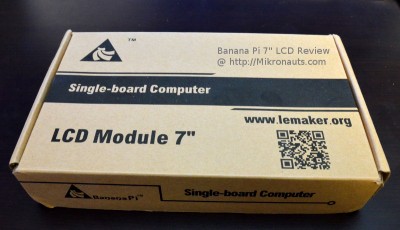
The 7″ LCD module arrived in a plain brown box – just like the 3.5″ display, albeit larger.
(click on image for larger version)
The panel was securely packaged in foam cut to place, and came in an anti-static bag.
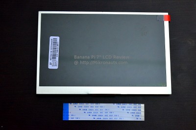
The 100mm 0.5mm spacing FPC cable was below the display.
(click on image for larger version)
Above you can see what the display module and cable looked like on top.
(click on image for larger version)
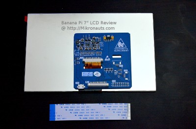
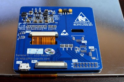
And here is the back of the display where you can see the adapter board.
(click on image for larger version)
I thought it would be useful to have a close up shot of the adapter printed circuit board.
Just like the 3.5″ display, there is space for a four pin resistive touch panel connector and controller.
There is also space for what appears to be a separate micro USB power plug, and a mysterious 16 pin 2×8 0.1″ pitch connector.
Article Index
