Hardkernel ODROID XU4 Shifter Shield Review
(click on image for larger version)
Software Compatibility
The ODROID-XU4 runs Linux – and thus supports the sysfs interface to GPIO.
Initially I had problems using sysfs for I/O, as I normally just use a sudo in front of the cat command for the export – however the XU4 requires using a root shell, invoked either with “su -s” or “sudo su”, before you can export GPIO’s.
Once odroid & mrdjr got me past that hurdle, I was happily blinking LED’s and reading inputs.
A few days later, a port of wiringPi was released, making the rest of my GPIO testing easier.
To install wiringPi for the XU4, execute the following from a terminal:
sudo apt-get update
sudo apt-get upgrade
sudo apt-get dist-upgrade
sudo reboot
then
git clone https://github.com/hardkernel/wiringPi
cd wiringPi/
./build
You can then use the ‘gpio readall’ command to see the current I/O settings and values.
Hardware Compatibility
The ODROID XU4 Shifter Shield has a 40 pin GPIO connector, designed to be compatible with the 40 pin GPIO connector on the ODROID-C1.
The first 26 pins are also electrically fully compatible with 26 pin Raspberry Pi expansion boards.
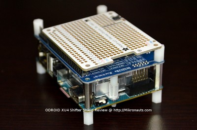
This means that it is also mostly compatible with the Raspberry Pi A+/B+2 40 pin GPIO header, so I thought it would be interesting to see how Adafruit’s popular 40 pin Raspberry Pi “HAT” would fit on the XU4 Shifter Shield.
(click on image for larger version)
As you can see above, the Adafruit HAT would fit fairly well, assuming that I’d already soldered the female header into it 🙂
Out of the four mounting holes, one does line up – the others could be used with shorter standoffs that would just sit on the Shifter Shield below.
Ok, now that we see how a 40 pin hat would mount, what should we look at next I wonder?
Blinking Lights… everyone needs (and loves) blinking lights!
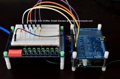
As soon as I saw the clear GPIO labels silk screened on to the XU4 Shifter Shield, I realized that (shameless plug) my SchoolBoard ][ development board would work great with an XU4 + Shifter Shield.
(click on image for larger version)
In case you are wondering why I put LED’s on the breadboard when there are LED’s on SchoolBoard ][ the answer is simple.
Hardkernel states that the GPIO is only rated to source/sink 4ma, and the SchoolBoard ][ was current limiting the LED’s to 5mA using 470 ohm surface mount resistors.
(I need to order some 1K SMD resistors, then I can offer SchoolBoard ][‘s with super bright LED’s that will draw less than 2mA)
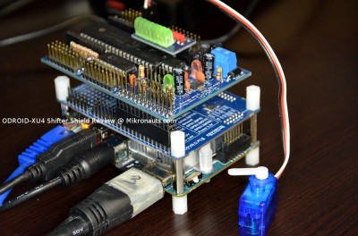
(click on image for larger version)
I was itching to try RoboPi on the XU4, as the XU4 is the fastest ARM single board computer I’ve tested to date, making it a great choice for robots that need more brain power.
RoboPi works great on an XU4 🙂
The serial port is on /dev/ttySAC0, and GPIO#174, once exported, can be used to reset RoboPi. My RoboPi C and Python libraries both worked immediately.


