Hardkernel ODROID XU4 Shifter Shield Review
More Software & Hardware Compatibility
(click on image for larger version)
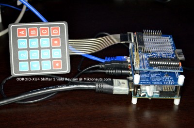
Next, I decided to test my Pi Rtc Dio expansion board – but without the RTC section, as the ODROID XU4 already has an RTC on-board.
I installed i2c-tools and python-smbus as follows:
sudo apt-get install i2c-tools
sudo apt-get install python-smbus
I then grabbed the sample code from my 4×4 I2C keypad article, and it worked! All I needed to do was change the smbus number from ‘1’ to ‘3’ in keypad16.py
joe keypad16.py
sudo python demo.py
(click on image for larger version)
As all Raspberry Pi add-ons assume 3.3V GPIO, I keep the XU4 Shifter Shield configured to 3.3V at all times.
I often use 5V I2C add-on modules with my Pi’s, and I usually use my Pi Jumper breakout board to do so, as it provides 3v3 and 5V four pin I2C interfaces.
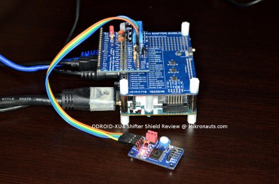
Using the odroid port of wiringPi, I was able to read the temperature, light dependent resistor and potentiometer on the small I2C PCF8591 module you see towards the bottom of the screen.
gpio load i2c
gcc -o ain test_i2c.c -l wiringPi -l pthread
./ain
No muss, no fuss – it just worked.
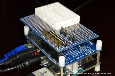
For some time I have been using an EZasPi prototyping board with one of those small 170 point breadboards for quick & dirty tests of small circuits, so I mounted it on the XU4 Shifter Shield.
It fits well, and if I add another standoff (in front of the white breadboard) it will sit nicely on top of the Shifter Shield.
(click on image for larger version)
For more complicated prototyping, I added a 40 pin stacking header (and a 5 pin one) and by mounting my EZasPie Proto 300 over the cabling, I can still read the GPIO labels on the XU4 Shifter Shield.
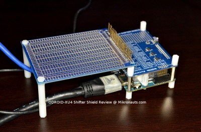
I can already feel another article coming, about what I am soldering onto the board shown below 🙂
(click on image for larger version)


