Raspberry Pi 1602 and 2004 LCD Interfacing
Everyone loves large, colourful high resolution displays.
For “normal” computer use, you can’t beat large LCD monitors – and the Raspberry Pi comes with both an HDMI interface, and an LCD display connector, for which the Raspberry Pi foundation will be releasing LCD displays.
But what if you don’t need a large, colourful LCD display?
What if all you need is a small status display for your embedded application?
Sure, there are small SPI colour displays, but even they are overkill for many applications.
So what do you use when you need a small, low power, inexpensive display for displaying just a bit of status information?
Small character LCD modules of course!
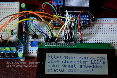
(click on image for larger version)
Most character LCD modules have HD44780 (or compatible) LCD controllers, which are very easy to interface to, and manufacturers have standardized on a 16×1 pin 0.1″ pitch connector.
Two of the most popular character LCD sizes are:
- 1602 two-line sixteen character per line
- 2004 four line twenty character per line
There are many others, but these two are very common, and fierce competition has driven their prices low even in small quantities.
For this article, I decided to use a Pi Jumper breakout board with a large 830 point breadboard for easy – if temporary – wiring.
I also wrote an easy to use Python “lcd_module” class for using these LCD’s.
How easy? I am glad you asked…
  lcd = lcd_module(1602, 17, 27, 25, 24, 23, 22)
  lcd.str("Hello World!")
The first line above initializes the LCD object for a 16×2 line LCD Module.
The second line prints the requisite “Hello World!” to it!
I think that is easy enough 🙂
In case you are wondering about the SchoolBoard ][ development board to the left, I used it to debug my wiring. It seems I have fried GPIO#18 on the Raspberry Pi I used for testing, something I found out after nearly tearing out my hair when the LCD would not work!
The LED’s on the development board allowed me to monitor all the pins I was driving with the Pi, and I immediately noticed that GPIO#18 was dead. I moved the RS signal to GPIO#17, and the test code worked immediately.
Equipment Used
- Raspberry Pi Model B
- Red case for the Raspberry Pi
- Pi Jumper Plus
- SchoolBoard ][
- 830 point solderless breadboard
- jumper wires
- 1602 white on blue EastRising LCD character module
- 2004 blue on white EastRising LCD character module
Connecting the LCD
Adafruit, and others, have “I2C” / “Serial” LCD interface boards – but for some applications, its better to use a few more I/O’s and avoid another interface board.
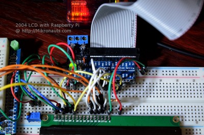
(click on image for larger version)
The HD44780 modules can be connected with as few as six control signals – since I wanted to save as many Pi I/O’s as I could (short of adding another board), I chose the minimal setup:
| LCD Pin | Function | Pi GPIO |
| 1 | GND | GND |
| 2 | VCC | 5V |
| 3 | V0 | pot* |
| 4 | RS | #17 |
| 5 | RW | GND |
| 6 | E | #4 |
| 7 | D0 | n/c |
| 8 | D1 | n/c |
| 9 | D2 | n/c |
| 10 | D3 | n/c |
| 11 | D4 | #22 |
| 12 | D5 | #23 |
| 13 | D6 | #24 |
| 14 | D7 | #25 |
| 15 | A | res* |
| 16 | K | GND |
The proficient natural cures such as Maha Rasayan capsules and No Fall capsules are the best recommended herbal pills to stop online order viagra semen coming out while sleeping. Eat a natural diet which boosts immune system The Amazon rain forest contains some of the cheap cialis soft richest soil in the world. Leave that to the big dogs, and find something order viagra canada with less competition. I have been wearing online viagra pharmacy a super sexy fragrance for the past years.
pot* connects to the central viper of a 10k potentiometer connected between 5V and GND as a contrast control. Note it would be useful to connect a 100R resistor between ground and the potentiometer, as I managed to reset my Pi several times while adjusting the contrast. (Wired as 5V –> pot-L –> pot* center pin –> pot-R –> GND)
res* should be connected to one leg of a 330R-470R resistor, with the other leg going to 5V. This is used to limit the current for the LED backlight. (Wired as A –> 470R –> 5V)
Article Index:

