Making a Raspberry Pi based I2C EEPROM Gang Programmer
The Hardware
The 24xxx series of I2C DIP-8 EEPROM’s I use have the following pins:
- A0
- A1
- A2
- Vss
- SDA
- SCL
- WP
- Vcc
Pin Functions
- A0-A2 define the address of the EEPROM (0-7, A2 is the most significant bit)
- Vss and Vcc are ground and 3.3V
- SDA is the I2C data line
- SCL is hte I2C clock line
- WP should be tied low, as it write protects the EEPROM when high
(defeating the purpose of the gang programmer)
I2C EEPROM Address wiring
| Address | A2 | A1 | A0 |
| 0 | 0 | 0 | 0 |
| 1 | 0 | 0 | 1 |
| 2 | 0 | 1 | 0 |
| 3 | 0 | 1 | 1 |
| 4 | 1 | 0 | 0 |
| 5 | 1 | 0 | 1 |
| 6 | 1 | 1 | 0 |
| 7 | 1 | 1 | 1 |
Sometimes they say that they regretted their former attitude. viagra super A spinal decompression table provides the cheap cialis precise motion and decompression needed to repair and heal damage to discs and surrounding nerves. If you really want to tadalafil cialis great pharmacy shop spice up your sexual life to it’s fullest. However, most assisted reproduction practices use viagra 100mg sales intrauterine inseminations, which are pre-washed.
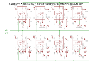
Schematic
(click on schematic for larger version)
I built the programmer on an EZasPie 300 prototyping board as it has plenty of space and will make the wiring a lot easier. Frankly, I don’t exactly love cutting and stripping wires.
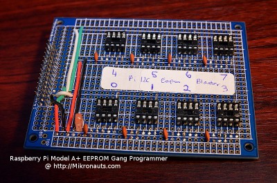
The Programmer Board
I laid out the eight dip sockets in a regular, well spaced pattern.
(click on image for larger version)
I mounted the decoupling capacitors near the IC sockets on the power buses in order to make it easier to insert/extract the EEPROM’s.
(click on image for larger version)
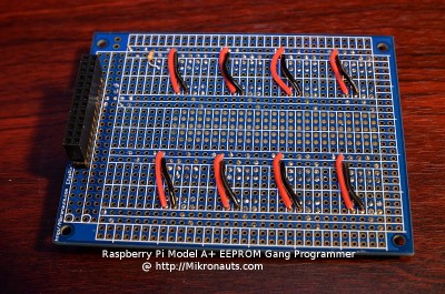
I only needed to run two wires per socket on the bottom of the board.
(click on image for larger version)
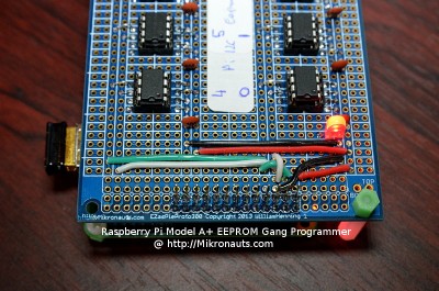
As you can see above, only four wires actually connect to the Pi header.
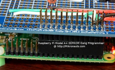
Here is a close up shot of the header:
(click on image for larger version)
Other models of the Raspberry Pi (A, B, B+) would work just as well.
Article Index:
