Raspberry Pi Zero (PIZERO) Review
Ethernet
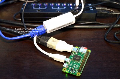
Below you can see the inexpensive 10/100Mbps USB 2.0 Ethernet adapter I tested with my Raspberry Pi Zero.

(click on image for larger version)
As you can see, I am back powering the Pi Zero from the Orico USB hub.
The 10/100 USB Ethernet adapter worked great connected directly or through the Orico hub.
It was very slow (~8.2Mbps) when connected via the cheap hubs, but came close to 100Mbps with the Orico hub.
I also tried the Linksys gigabit USB 3.0 adapter I used in my Raspberry Pi 2 review – it worked well directly connected to the Pi, or via the Orico hub – but unlike on the Pi 2, it was not any faster than the 10/100 USB2 adapter.
GPIO
WiringPi
I got an error message when trying to ‘gpio readall’:
pi@PiZero:~ $ gpio readall
Oops – unable to determine board type… model: 0
I installed the latest wiringPi from git, and after rebuilding it, I still had the error above.
Fortunately the gpio utility was able to set pin modes and read/write I/O, and the C library worked as well.
UPDATE:
I emailed Gordon last night, and he had uploaded a new version of WiringPi fixing ‘gpio readall’ between the time I tried it above, and the time I published the review 🙂
After downloading v2.31, it built without issues and ‘gpio readall’ works fine!
Thanks Gordon!
pigpio
I simply followed the instructions on the download page:
wget abyz.co.uk/rpi/pigpio/pigpio.zip

unzip pigpio.zip

cd PIGPIO

make

sudo make install
pigpio installed, compiled and worked well.
Add-On Boards
Whenever I review a board, I test some hardware products on it to see if they are compatible.
RoboPi
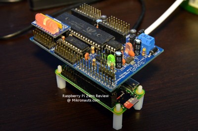
As expected, the Raspberry Pi Zero “just worked” with RoboPi.
No muss, no fuss.
Mind you, you can see that RoboPi just dwarfs Pi Zero, which looks like an add-on to RoboPi!
If you are interested, you can learn more about RoboPi from the product page – including downloading and read the user manual.
All I had to do was install the C/C++ & Python libraries from the product page.

(click on image for larger version)
Here is the Python code for the “Cylon” style LED display above:
#!/usr/bin/python import RoboPiLib as RoboPi import time as timeRoboPi.RoboPiInit("/dev/ttyAMA0",115200)for led in range(16,24): RoboPi.pinMode(led, RoboPi.OUTPUT)while 1:for led in range(16,24): RoboPi.digitalWrite(led,1) time.sleep(0.2) RoboPi.digitalWrite(led,0)for led in range(16,24): RoboPi.digitalWrite(39-led,1) time.sleep(0.2) RoboPi.digitalWrite(39-led,0)
Please excuse the quick-and-dirty nature of the code above.
The I/O range used for the LED’s was 16..23, which is why the index is subtracted from 39 to go in the reverse direction (as 16+23 = 39)
Article Index
- Introducing Raspberry Pi Zero
- A Closer Look at Pi Zero
- Feature Comparison, Operating Systems, Software Compatibility
- Common Applications, Multimedia, Kodi, Hardware Compatibility, USB Hubs, WiFi
- Ethernet, GPIO: WiringPi, pigpio, Add-On Board testing, RoboPi
- More testing: Pi Droid Alpha, SchoolBoard ][, Pi Rtc Dio
- More testing: Pi Jumper, EZasPi, Benchmarks: Booting & Launching Apps, Compiling GNU Emacs
- More Benchmarks: SysBench 0.4.12, iperf client & server, NBench 2.2.3
- More Benchmarks: Unix Bench 5.1.3, hdparm, dd, Power Utilization, Documentation
- Support, Conclusion, What I liked, What I did not like