The Better MouseTrap Servo Tester
May 27, 2014
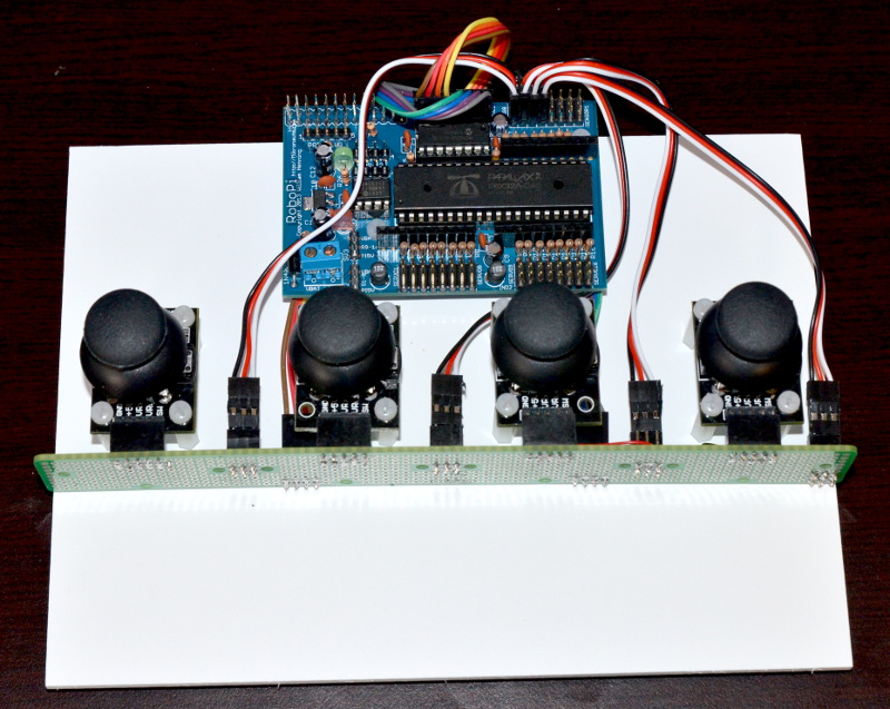
Here is what the “better mousetrap” servo tester looked like at the start of this journey:
(click on the image to see a larger photo)
RoboPi and the joystick modules are mounted on stand offs, which are mounted on the white Sintra board.
RoboPi can control 16 (actually 24 with care) servos directly, but it only has eight analog inputs, without adding a multiplexer or another ADC.
Each joystick goes to two analog channels, and the “hat” pushbutton of each joystick goes to digital inputs – you can think of it as a 12 channel controller (eight analog + four digital channels).
In order to avoid having to add more joysticks, or a multiplexer, I decided to use the switch on the thumbstick to switch between two different sets of channels – providing 16 virtual analog channels!
All joysticks are reading properly, however I had to add pull up resistors to the output of the switches as the module manufacturer left them off their PCB’s.
The auto-calibrate routine and mapping the joystick ranges to 500us – 2500us servo signals, with a dead-zone around the 1500us centre point work fine.
Joystick analog pin map for RoboPi
- AIN0 – js0 X axis – servo on P0 and P8
- AIN1 – js0 Y axis – servo on P1 and P9
- AIN2 – js1 X axis – servo on P2 and P10
- AIN3 – js1 Y axis – servo on P3 and P11
- AIN4 – js2 X axis – servo on P4 and P12
- AIN5 – js2 Y axis – servo on P5 and P13
- AIN6 – js3 X axis – servo on P6 and P14
- AIN7 – js3 Y axis – servo on P7 and P15
Joystick button digital pin map for RoboPi
- P20 – js0 toggles servo P0&1 vs P8&9
- P21 – js1 toggles servo P2&3 vs P10&11
- P22 – js2 toggles servo P4&5 vs P12&13
- P23 – js3 toggles servo P6&7 vs P14&15
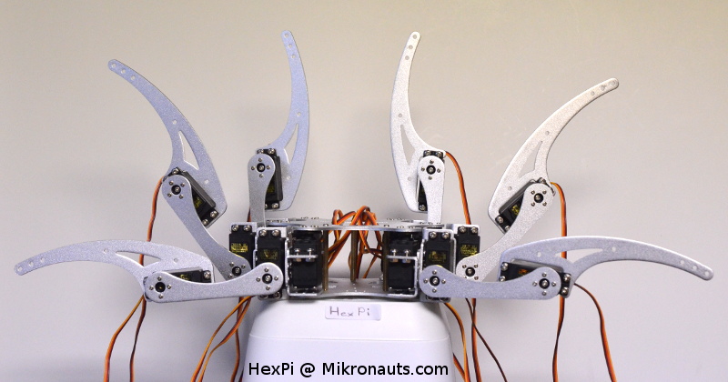
Here is HexPi with all his legs mounted – you can see why TBMST (The Better Mousetrap Servo Tester) will help me.
(Click on the image to see a larger photo)
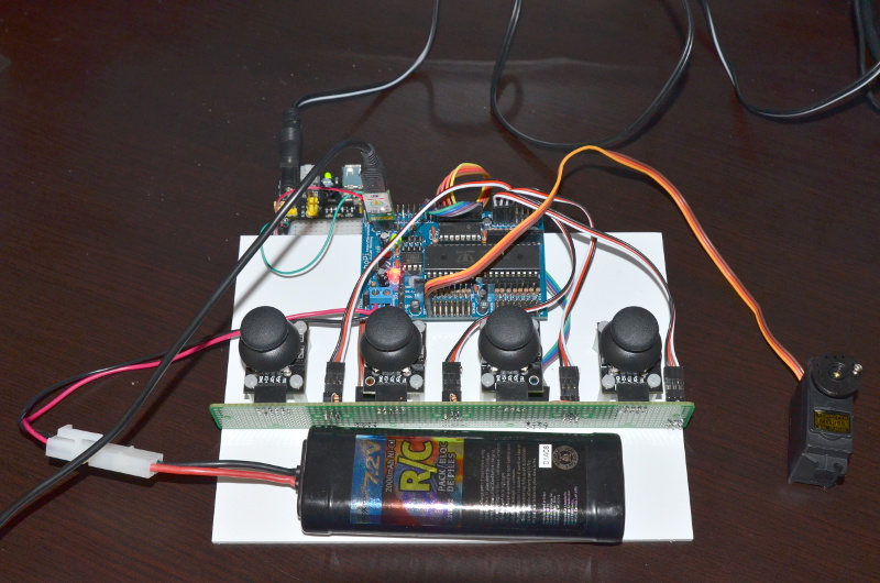
Here is a photo showing the current state of my servo tester project:
(Click on the image to see a larger photo)
As I did not want to power the servo tester from a wall-wart, I went on an archaeological dig in my lab… and I found my two 7.2V RC battery packs and chargers; I will use them to power the servos for now. Later I will probably switch to two 18650’s in series.
I’ll power RoboPi from a nice “USB Charger” battery pack, or some other regulated 5V power supply. For now I am using one of the inexpensive “breadboard power supplies” as you can see on the upper left of the photo.
More updates soon!


